")
Receive our Newsletter
to stay informed: about updates, new products and solutions or exhibitions and conferences.
Subscribe to our Newsletter


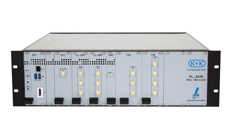

The KL-3400 Real Time Clock is developed and designed by K+K Messtechnik GmbH in cooperation with Lange-Electronic GmbH with support from Physikalisch-Technische Bundesanstalt, Braunschweig, Germany, with financial support from Federal Ministry of Economics.
Software clock algorithms are well established, e.g. in combining stable atomic clocks that are actually scattered all around the world, to form virtual time scales (like UTC), which are normally distributed to users by bulletin in retrospect only.
In contrast to such ‘paper clock’ approach, we have investigated the hardware requirements and actually built what we call a ‘real time clock’, i.e. a device, which accepts the output signals of various stable clocks and optionally a 1PPS timing signal (plus possibly some bulletin information and strategic operator decisions), and from these generates an optimised output clock signal under the control of software clock algorithms.
Is to provide a stable clock signal based on
The clock will continue its stable phase track if one or even a few of the contributing clocks fail.
Compared to the first clocks these have only one calculation mode
while the new clock owns 2 completely independent calculation possibilities.
This can be used to work with 2 different steering modes to find out
which mode is better suited to which clock.
It can also be used to select the different modes to find out which steering calculation fits better.
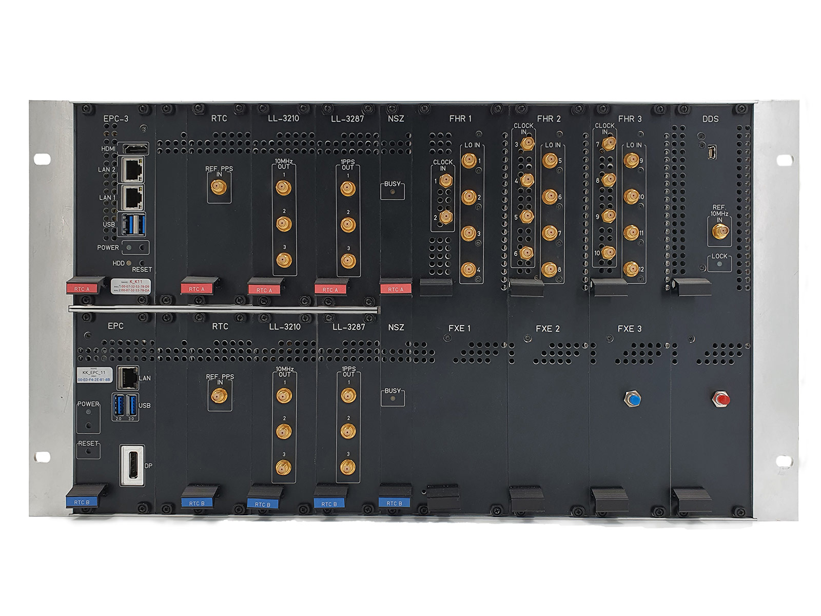
Up to 15 external clocks can be connected
Two independant calculations possible:
The lower part with OCXO B and NSZ B works with our programm,
the upper part (OCXO A, NSZ A) can be programmed by the user with his own programme.
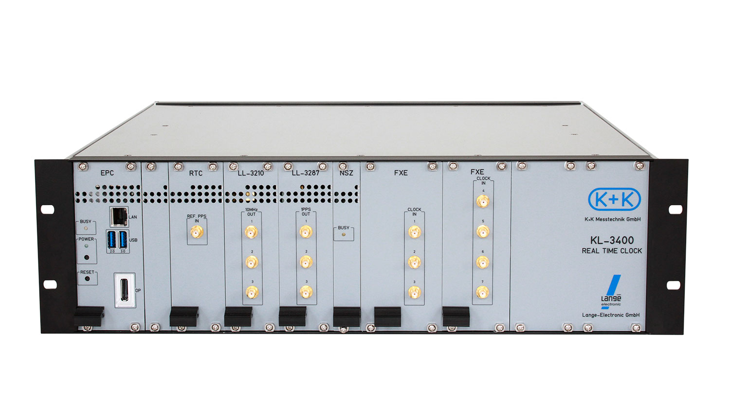
Up to 4 multi-channel Synchronous Phase Meter boards are concatenated to provide simultaneous phase measurements from 4 to 11 clock sources:
An (optional) Scrambler is available to assure highest performance – it reduces errors originated by the relative phase between the channel inputs an the 10MHz reference signal to less than 10ps.
Key features of FXE relevant to this application are:
The 10 MHz frequency doubled OCXO signal is internally delivered to the phase meter both as the reference signal and as input to its channel 0.
The inputs to channels 1.....15 are connected to front panel connectors to accept 5 MHz or 10 MHz clock signals (phase readings from 5 MHz input signals will automatically be doubled by the software to be immediately comparable to readings resulting from 10 MHz
input signals).
Every 100 ms the FXE reports the phase difference of each of the clock input channels to channel 0 (i.e. the phase difference between each of the atomic clocks and the OCXO).
In detail, reported phase differences are the average of 100 measurements taken at 1ms intervals. Additionally, a continuously incrementing 'number of measurement' is included, which serves as a time stamp within the PC data processing.
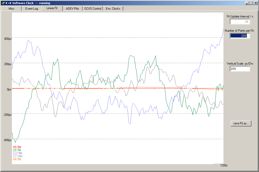
Software controls the OCXO that it generates a smooth and stable time scale based
Basically the OCXO's phase is locked to the weighted mean of the contributing atomic clocks.
Without inclusion of GPS/GNSS 1pps both phase and frequency would be arbitrary.
To provide long-term absolute timing accuracy, a slowly varying time offset resulting from the 1PPS TIC measurements (with a time constant of typically several days) is added to the weighted mean of clock phase offsets.
A manually entered time and/or frequency offset may be added to the TIC results to compensate for cable delays etc.
An initial 'learning' session is required during which all contributing clocks must be OK for the SWC to start properly.
The parameters for linear fits of each clocks' phase difference to the OCXO's phase versus time are being established for the first time. Actually it is during this initial learning session that the future phase and frequency of the SWC time are being established.
If one of the clocks exhibits a phase jump or a change in frequency large enough to be observable its fit parameters will no longer be updated, but instead will be frozen.
The phase control loop will no longer use that clock's actual (faulty) measured phase difference data, but instead will replace them by the value estimated from the frozen linear fit parameters.
Thus the time evolution will continue to follow the same phase track as it did before the fault; the time scale realized by the SWC will continue without a change in phase or frequency.
The faulty clock's phase will continue to be measured against the OCXO phase, and the data will continue to be checked for phase steps and for Allan deviation. If, after a reasonable time of observation, no further anomalies have been observed, the clock is considered healthy again and a new initial set of linear fit parameters is determined.
The management of the clocks is described by the combination of three attributes: Mode, Status and Health.
MODE
'include' means that the clock is contributing to the Ensemble average - either (if it is considered healthy) with its latest measurement results, or otherwise with data estimated from the fit.
'monitor' describes the mode where a clock's measurements are continuously evaluated to check for faults and to update the fit in regular intervals, but that clock does not contribute to the ensemble time, and hence has no influence on the OCXO control.
'ignore' means that data for that clock are not being considered at all.
STATUS
„known“ means the respective clock has been measured sufficient long time without a fault, phase and frequency offset could be determined from past measurement data.
A clock that has not been continuously measured or has shown a fault is put into status „learning“.
Right after the start of the software all clocks are assigned the status „initial“.
HEALTH
Normally the health value of contributing clocks will be „good“, the fit papameters will be updated regularly and that clock will contribute to the ensemble time.
At the start of the software the status of all clocks is set to „dubious“. This coincides with the status „initial“ and is valid only right after the start of the software.
If either a phase step or a change of frequency relative to the ensemble time is observed the health will change to „faulty“, the updating fit will be suspended and the last good fit parameters will be used.
to stay informed: about updates, new products and solutions or exhibitions and conferences.
Lange-Electronic GmbH
Rudolf-Diesel-Str. 29a
82216 Gernlinden
+49 8142 284582 0